When I first moved out to Philly I gave up a lot of projects and space, I have always worked with my hands so it was hard to let of of having a mechanic shop at my disposal. I knew that I needed something to keep me busy, so I bought a 3d printer.
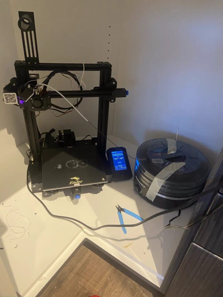
Most people’s first printing project is to print upgrades for their printer. Or as some say, printers print prints for their printer. I wanted something larger, and right around the time I got my printer I also snagged a turbocharger from the dumpster at work.
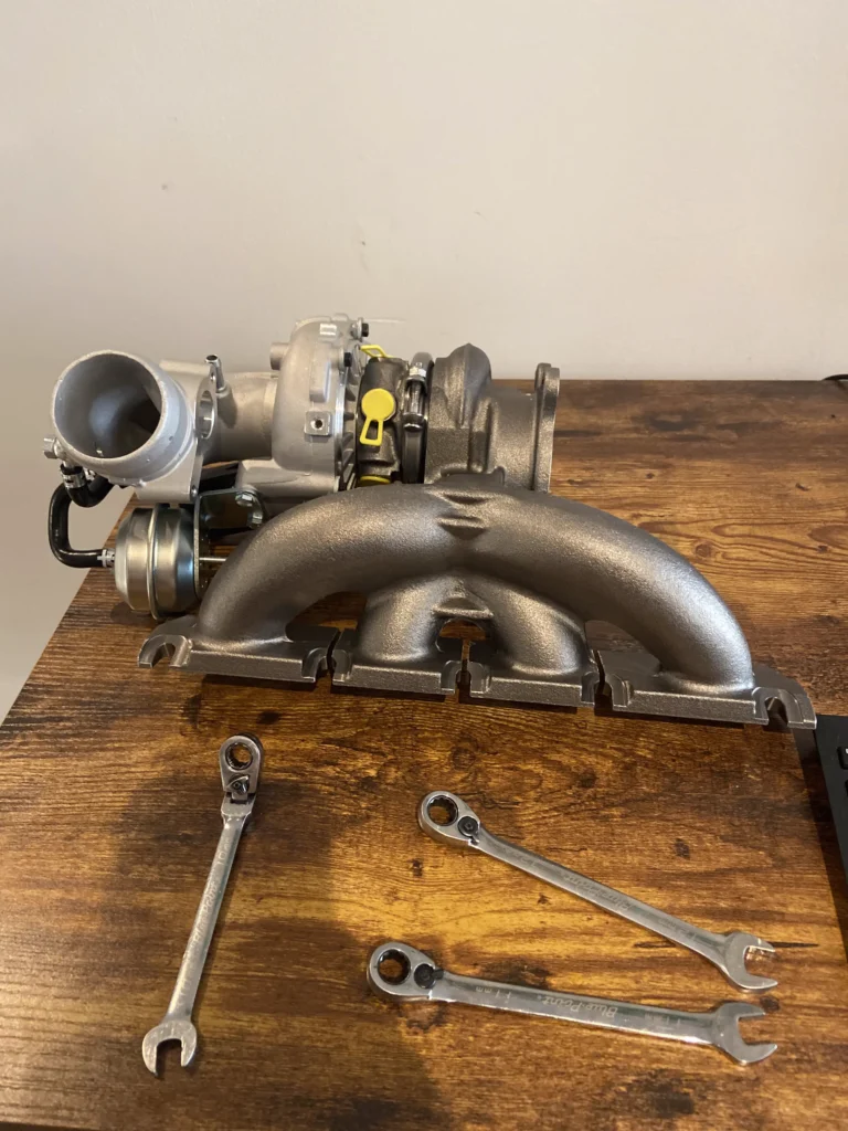
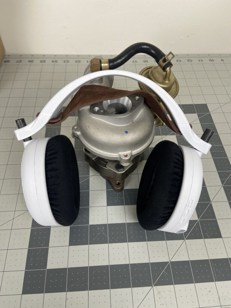
I would have loved to use the turbo for its intended purpose but I no longer had a fleet of motorcycles, so I had to come up with another use. I decided I wanted to build an electric ducted fan that uses the compressor turbine as its fan. This meant that I had to tear apart the turbocharger and find a way to house the turbine, power it and collect the compressed air.
In the above pictures you can see that I modeled the turbine as a solid piece instead of modeling the individual blades, they were not necessary for modeling the rest of the housing. I also modeled an rc motor that puts out just over 1.5hp and can spin up to 30,000 RPM. I chose this motor because it reaches the high RPM that the turbine would reach when used in the turbocharger. In order to connect the turbine to the motor I used the original turbine shaft cut down to length, and used a flex adapter to adapt the 4mm motor shaft to the 8mm turbine shaft.
Looking at the image on the left you can see that air enters the turbine from the opening on the left, the turbine then compresses and throws the air sideways into the main body. The outside wall and inside body are used to guide and collect the air, pushing it against the motor to help cool the motor, and finally sending the compressed air out the back. This initial design had a bell housing style exhaust, this design is commonly used for rocket motors where trust is produced from combustion but is inefficient and reduces the total trust on a design like this.
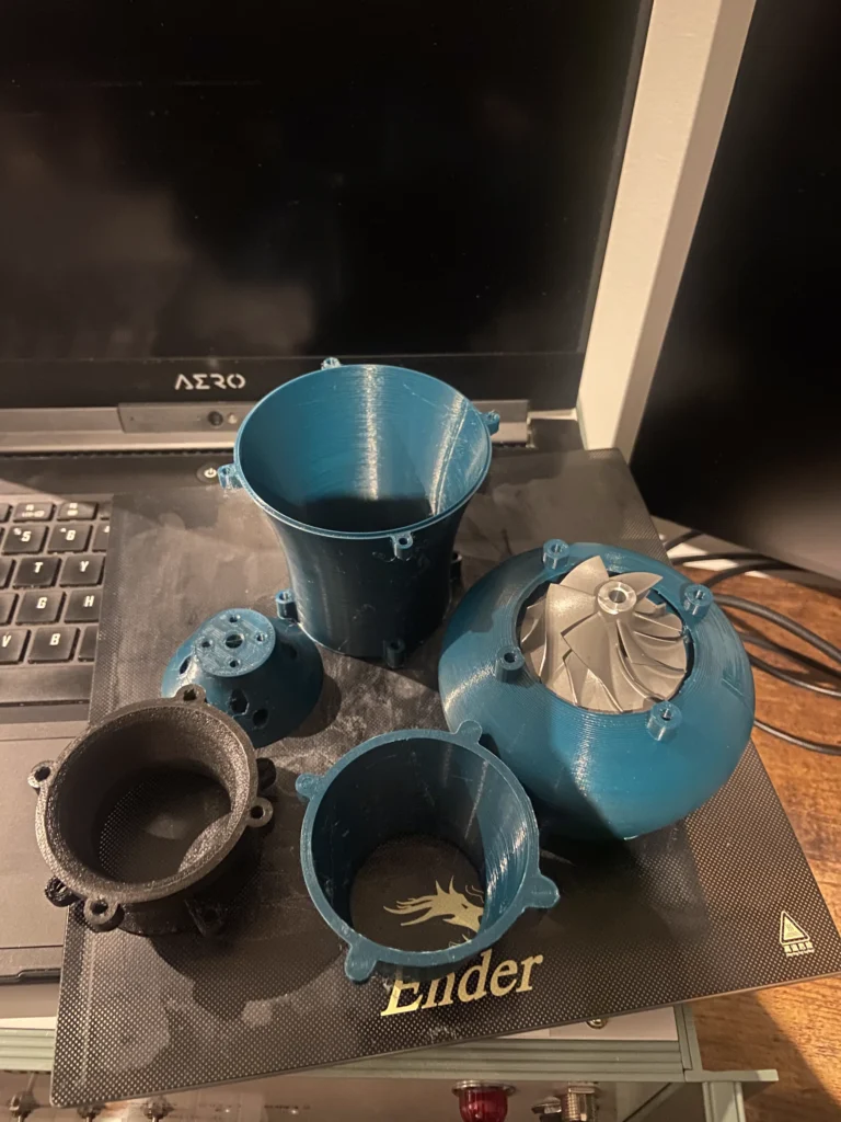
Above you can see a better view of how the air enters the turbine and is thrown horizontally. You can also see how the printed components are connected, I designed these bolt hole tabs that protrude from the main body, the lower tabs have heat set brass threaded inserts and the top are just a through hole to allow an M3 bolt to pass through and clamp the two prints together.
In order to test this build I printed a stand that bolts on to the front and holds the assembly upside down. This points the thrust into the ground, or in my case into a scale which I used to measure the thrust. I used a Dewalt power tool battery to power the RC motor and spun it up to full throttle, the maximum thrust I recorded was ~280 grams which is sadly only half of the total weight. Even though the build has a pitiful thrust to weight ratio of .5, there are many design aspects that can be fine tuned to increase the thrust.
For example, the output nozzle diameter is significantly larger than the inlet. I have printed a couple of different sized outlets of varying diameters to test if a reduction in size will increase air velocity and thrust. I also noticed that the air swirls out of the nozzle, I believe that a lot of the thrust is lost by having the air exit the nozzle sideways instead of linear with the thruster, the addition of stators or air directing fins inside the assembly can reduce this issue.
If you want to learn more about this build, or hear it scream at 30,000 rpm, you can watch the Youtube build video below.
