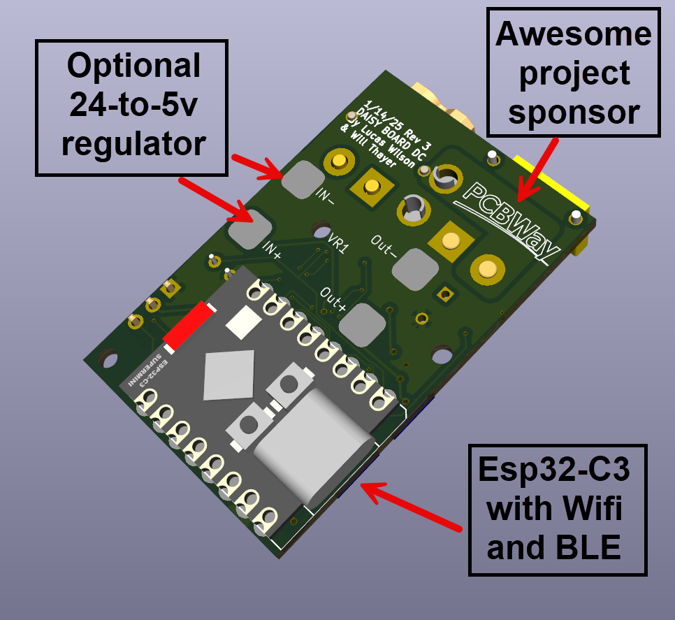
Description
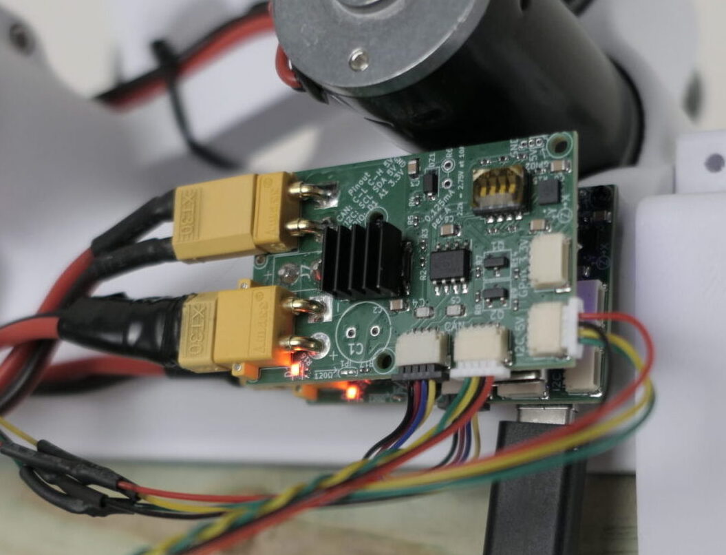
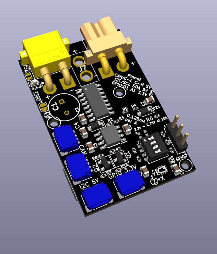
An incredibly feature-filled DC motor controller board that I designed for my custom quadruped robot dog. Read the whole story on the DaisyBoard build log.
Features
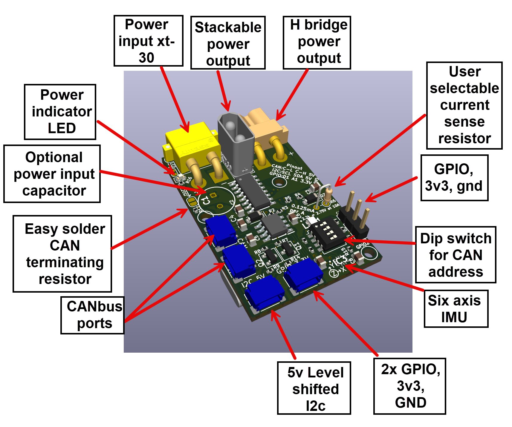
- 5–24V DC input through XT30 or a USB-C port
- XT30 power output for stacking or daisy-chaining boards
- H-bridge motor controller: forward/reverse and full PWM range output through XT30
- Pad for a current sense resistor of your choice
- Two CAN bus ports (TJA1050T transceiver) for daisy-chained communication between boards, with a built-in 120Ω terminating resistor on a solder pad
- DIP switch resistor network to set the CAN address externally (up to 16 addresses)
- 5V level-shifted I2C port compatible with Adafruit STEMMA QT and SparkFun Qwiic
- JST-SH 4-pin port with power, ground and two GPIO pins, plus a 3-pin header with 3.3V, ground and one GPIO
- Built-in six-axis IMU
- Runs on an ESP32-C3 SuperMini for Wi-Fi and Bluetooth
The KiCad files and BOM are open source, so you can also order boards yourself from a PCB assembly company; the build log has step-by-step PCBWay ordering instructions.
Will Thayer –
We the designers of the DaisyBoard-DC recommend the DaisyBoard-DC