Thin film deposition is a technique used to coat a material, often glass or silicone, with a thin layer of a substance measured in the nanometers. Deposition is used to create the layers of conductive traces inside microchips, coating the mirrors and lenses in telescopes, inside our touchscreens and many more places. It is so critical to our modern world that we wouldn’t have a modern world without it. But why would anyone want this tool in their home lab?
I found Physical Vapor Deposition (PVD) incredibly interesting from the day my brother introduced me to it back when I was in high school and he had gotten a job in this field. Upon learning about it I researched what its used for and what you can do with it. Stumbling upon Youtube channels like Applied Science who used his PVD chamber to coat bugs in a layer of silver to make them optically reflective to his home made scanning electron microscope, and The Thought Emporium who used his simple PVD chamber to coat microscope slides creating a conductive pattern that was used to interface with hamster brain cells.
PVD works by creating a chamber void of air, boiling or blasting atoms of your donor material and allowing those atoms to condense on the surface of your target. There are two main styles that are achievable for a home lab: Ion sputtering and hot boat boiling. Hot boat uses a tungsten sheet heated to hundreds of degrees C to melt your donor material, your donor material in liquid form then boils off atoms which creates a mist of atoms in your vacuum chamber that then condense on the surfaces inside the chamber. Ion sputtering uses high voltage to smash electrons into your donor material, breaking atoms off the donor and spraying them into the vacuum chamber. Sputtering can be used for materials that break down in high temperatures but it is far more complicated and finnicky to get working. With both styles, the atmosphere inside the vacuum chamber is highly critical. Not low enough pressure means that coating will not occur at all, and even the slightest presence of oxygen can rapidly oxidize the mist before it reaches your target surface. At the time of building this project I knew these limitations but did not understand just how critical they were.
In order to build my own PVD chamber I needed a large chamber that I could pull a vacuum on, and a vacuum pump. After some searching I found a perfect glass bell at Hobby Lobby for twenty dollars, I also purchased a vacuum pump off of ebay and later purchased a second and third from a garage sale to help speed up the evacuation of gas. I built a stand out of two by two wood poles from harbor freight and wired in a couple light switches to control the pumps and power supplies
To attach my pumps to the chamber I used off the shelf steel plumbing pieces and reinforced rubber hose, sealing them using silicone. If you know anything about high vacuum you know this was a major mistake. Even though you may think of silicone and rubber as water tight, they are very permeable to gas. This problem is accentuated by the fact that the PVD process is very sensitive to the pressure of the system. Now for my second major blunder. I wanted the glass chamber to sit on a hard surface that I could drill through and add electrical and gas passthroughs to, and due to the limited tools and limited knowledge I had back in high school I decided that a large slab of high density polyethylene would work. This is the same material that cutting boards are made from and because they are plastic they also suffer from outgassing and being gas permeable. Because of this, even with three vacuum pumps running at the same time I was barely able to evacuate enough gas to get the chamber down to proper vacuum pressures.
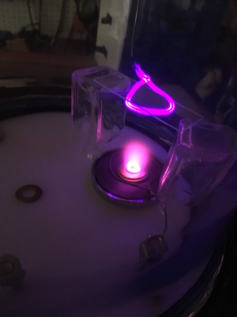
Even so, it was low enough to look cool and start testing. My first attempt at PVD was to build a sputter coater, and for this I had to build a high voltage power supply. I first used a neon sign transformer at 12Kv but even that wasn’t high enough, plus it had to be DC and the transformer put out AC. So for my second power supply I used a flyback transformer scavenged from the back of an old CRT tv. These are capable of producing 20-30Kv DC, and paired with a ZVS driver from an induction heater, (another project I have to write about) you get a cheap variable high voltage power supply. The donor material, copper, was then placed on top of a magnet attached to the anode. This circular magnet helped guide the plasma to the center of the donor material which can be seen below. Then when high voltage is applied electrons flow from the cathode to the anode, bombard the donor material scattering copper atoms throughout the chamber where they land on the surface of the microscope slide. At least thats what I expected to happen, but so many variables were so far from right that there was no chance of this working. At least it looked pretty cool
With that having almost no chance of working I moved on to the second technique, tungsten hot boat. For this method I needed to build another power supply but it had to be the complete opposite from the first one. While Sputtering requires crazy high voltages putting out tens of milliamps, the energy required to heat a tungsten strip white hot requires 2-3 volts at nearly a kiloamp. For this power supply I took apart an old microwave oven, if you didn’t know microwave ovens contain a massive medium-high voltage transformer that can put out some scare power. I cut out the secondary winding of the transformer which consisted of thousands of turns of thin gauge copper wire and replaced it with three turns of wire stolen from a car jumper cable. This allowed the transformer to put out a measured 2.3V at enough amps to melt a quarter inch steel bar. On top of the tungsten sheet I placed a small trimming of brass, pulled a vacuum and turned on the high current power supply.
Though you cant see it in these images, the walls of the glass chamber eventually started turning a muddy brown color which decreased in opacity as it got closer to the tungsten boat. Although I don’t have photographic proof, I measured the surface of the microscope slide with a multimeter and found it had a measurable, repeatable resistance. Even though that sounds successful it wasn’t, I believe I had just coated it in brass oxide instead of plating it with a layer of brass. This is as far as this project went, there were too many things that needed changing in order to get it to work properly. Some day I really hope to revisit this project, as it opens the door to so many other interesting builds.
