Like most of my projects, this one started by becoming inspired after watching a Youtube video. Specifically This video from BreakingTaps about rolling contact joints in replacement of bearings and This video made by Aaed Musa about capstan drive in replacement of gear drive. I highly suggest you watch both of these videos to better understand why I became so inspired by their designs.
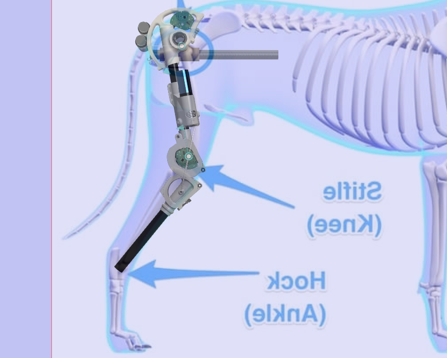
Update 1/15/25
The leg moves!
About two weeks ago I received the latest revision of custom designed motor controller boards from PCBWay and they are amazing. To list some features:
- 5-24v dc input by xt-30 OR usb-C port
- xt-30 power output for for stacking or daisy chaining boards
- An H bridge motor controller for forward/reverse voltage and full PWM range output though xt-30
- Location for a current sense resistor of you choice. Dependent on your application
- Two CANbus ports for daisy chaining communication between boards using a TJA1050T CAN transciever
- A built in 120OHM CANbus terminating resistor on an easy to solder pad
- A dip switch resistor network so you can set CAN address externally. Easily set up to 16 addresses
- A 5v level shifted I2C port compatible with Adafruit Stemma QT. And with a 1-2mm JST jumper you can also use Adafruit Stemma and SEEED Grove devices
- A JST-SH 4 pin port with power, ground and two GPIO pins. This port can also be used as non level shifted I2c
A three pin header with 3.3v, ground and a single GPIO pin - A built in six axis IMU
- ESP32-C3 with built in Wifi and Bluetooth
- Three mounting holes
An optional solder on 5v regulator. Only one of these is required per a daisy chained set of boards
The way I am using these boards is each one controls one joint. The joint controller reads the joints current angle from the as5600 magnetic encoder over I2C, and uses a PID loop to adjust the motors PWM value to approach the target angle. Each joint controller receives its target angle (along with a number of other message it can handle) over CANbus. An extra motor controller board is used as the CANbus master and sends target angles every 50ms. The master receives the target angles over serial, and right now I am using a Python GUI with sliders to manually control each joint. Its kind of like that old game QWERTY where you tried to make a person walk by manually controlling their leg joints. I also have a record and playback function where I can turn the motors off, manually move them by hand and record the movement then play it back.
We’ve been calling these new motor controller boards DaisyBoard because of how easy it is to daisy chain and stack them. Below you can see Daisyboards in some 3d printable cases I have been designing and a view of what a quad stack looks like. Since each board has a 24v xt-30 input and output you can stack them basically as high as you want and they will all share input power. The limiting factor is how much current the traces can handle and I haven’t found that yet even when stalling the 5 motors used on my leg
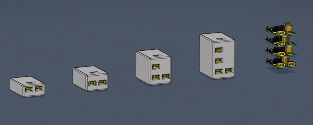
Thank you so much to Zoe from PCBway for hooking us up with our first batch of DaisyBoards.
These boards are fully open source. Click the link below to learn even more about the daisyboard, and find them for sale in the store! Links to download the entire leg CAD model are at the bottom of the page
Capstan's and Rolling Contact Joints
The video from BreakingTaps is what originally caught my attention. The rolling contact joint became so interesting to me not because of its lack of bearings but because of its similarity to how real biological joints work. A human knee doesn’t just pivot around a single point like a bearing, it rolls on a surface with a changing center of rotation. This has the interesting benefit of increasing the length of travel a tendon will take for the same angular change. Meaning a rolling contact joint’s tendon will have to be pulled further than a bearing joint’s tendon. This gives the rolling contact joint a mechanical advantage, like lowering a gear ratio. The other main reason I became enamored with the rolling contact joint is because of its relative simplicity and beauty. It has such an organic movement and when paired with a tendon drive system you can’t help but feel like its straight out of science fiction.
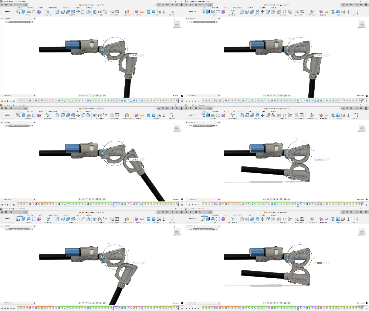
After falling in love with the rolling contact joint, I discovered Aaed Musa’s capstan video. Capstans are drums with rope wound around them which can be spun in order to pull the rope. They are often used on sailboats to hoist a sail or other heavy objects. They are similar to a winch used on an off road vehicle except the key difference is that a winch winds up all the rope whereas the capstan winds up rope on one side and spits the excess out the other
Aaed’s video goes into great detail about using this drive in a robotic dog chassis. He points out how a capstan of one diameter driving a capstan of a different diameter creates a gear ratio while using no gears. I took to this design because I felt it paired perfectly with the rolling contact joint for a number of reasons: both concepts use rope in their operation, both combined create a tendon/joint structure with similarities to real anatomy, and both are novel and not seen often in the world of robotics.
A large benefit of a capstan drive over just a winch is that it can be driven forwards and reverse. If you used a winch which just coils rope around its drum you would need one winch to extend the joint straight and another to bend the joint in. By using a capstan which feeds the rope out the back you can use a single motor to drive the joint in both directions.
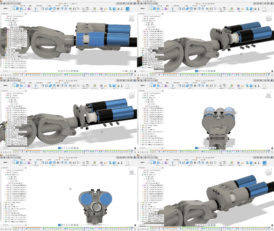
One difficulty faced when designing around a capstan drive is motor placement and packaging. Typically you have the motor sticking off the drum linearly (unlike the image on the left of the gray industrial capstan). I didn’t want my robot dog leg to have a large motor sticking off the side, so I turned my capstan sideways and used pullies tangent to the drum to redirect the rope towards the joint. In the video below you can see my dual motor(blue) capstan drive, along with the capstan drums (light gray) and the pullies which redirect the rope (dark gray with m4 bolts through them).
Electrical and motors
Another unreasonable goal I have set for myself for this project is to try and build it on a budget. The majority of open source quadrupeds seem to use BLDC motors (like those on rc quadcopters, cars, boats), stepper motors or servos. Steppers are expensive, non efficient, and don’t offer a great strength to weight ratio. Servos are also pricy when your torque requirements are high, noisy and they tend to wear out. BLDC motors are efficient and powerful but they are very expensive and require more advanced circuitry to control them. For single joint you can expect to pay $40-100 for the motor and $90-250 for a motor controller such as O drive. Such an expensive motor controller is required for BLDC motors because unlike steppers and servos they are not positional motors. BLDC expect to run fast and continuous usually in a single direction, in order to use them in a system where they have to rotate a certain amount of degrees then hold that position you have to use non open source complicated controllers. And on top of all that there are three to four motors per leg, each requiring its own motor controller. On the low end a single leg may cost around $500.
My solution is to ditch the standard and go back to simplicity. I have decided to use cheap off the shelf DC motors with planetary gear sets. DC motors just require a voltage applied to their input wires and they spin, no fancy three phase AC or complicated stepper control. They are also cheap, the motors I am using cost $16-18 each on Aliexpress. They may not be as efficient as the BLDC nor do they have the positional accuracy of the stepper or servo, but combined with a planetary gearbox to drop the output speed and use of PID control to target and hold an angle they are a great cheap compromise.
Speaking of using these to target an angle, you may have thought to yourself that DC motors share the same issue as BLDC in that their typical use case is to just spin, not hold a specific angular position. My solution to this may sound complicated but in practice it is far simpler than using a BLDC. In order to control the motor I am using a custom made circuit board (PBC) which has an Arduino pro mini, potentiometer and motor controller attached (along with other items). The Arduino will receive a signal telling it what angle to target, it will read the joints current angle from the potentiometer and use a PID algorithm to determine how much power to send to the motor to get it to that angle. This is called closed loop control, the Arduino is constantly reading the angle and adjusting the power sent to the motor in order to reach its target.
Below you can see a front and back side render of the custom PCB designed by Will Thayer who has been a massive help on this project
Below lists all the features Will was able to fit onto the board
- Arduino pro mini
- Mounting holes
- H Bridge Motor controller IC (VNH7100BASTR)
- 2X 4 pin I2c port
- Potentiometer
- RGB led
- 24 to 5v voltage regulator for the Arduino
We are using I2c communication because it is built directly into the Arduino and the library to use it is very easy to work with, though you may have realized the problem with using I2c. I2c is only capable of very short transmission distances, typically under 10 centimeters, to solve this we added an I2c booster chip which will allow us to communicate to each leg even over the 4 meters combined.
Up until now I have only talked about the knee, which is the first joint I designed and started iterating, but the hip and hip flexor joints have also been under way while I dial in the knee. The hip joint will use the same custom circuit board as the knee. The hip flexor and the ankle joint will use a different shaped board with all the same features, this is to get the board packaged better for these more difficult joints.
We have ordered and tested version 1 of the board, pre assembled at a cost of $28 for 5. Version 2 which is what I described above will cost $30 for 5. The entire robo dog will require 8 of this board and 8 of the other style board which should cost around $120 in total, all arriving mostly pre assembled. Hell of a lot better than $80 per motor if using O-drive.
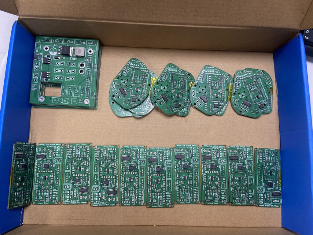
Update 9/11/24: All boards have arrived. In the top left you can see the raspberry pi power distribution and I2c master board. Top right the version 2 knee board, and bottom the ankle boards. We have not yet tested the I2c booster chip but we went ahead and ordered enough boards to build one complete robodog, I’m still a little nervous about this but I have high hopes everything will work
Code
I thought the code was going to be quick and easy, at first I had only planned for the joint to receive a target angle then PID to it. But Will pointed out what else I could do with different I2c commands and it snowballed a bit. Below is a breakdown of the codes features followed by the code itself
- PID Control: Utilizes a PID loop to control motor output based on the potentiometer’s input, managing the motor’s speed and position.
- EEPROM Storage: Stores and retrieves PID tuning parameters, deadzone, and calibration data (min/max potentiometer values) from EEPROM.
- Safe Mode: Activates if no I2C communication is received within 2 seconds, disabling the motors and setting the LED to red.
- Calibration Function: Sweeps the motor to determine and store the min and max potentiometer values.
- I2C Communication: Receives commands for setting the target angle, calibrating the motor, adjusting the dead zone, entering safe mode and rebooting the Arduino.
- Motor Fault Detection: Monitors the CS pin for fault conditions.
- LED Feedback: Provides visual feedback for different system states (initialization, normal operation, safe mode, motor stall).
- Motor Control: Manages forward/reverse motor control based on PWM signals and dead zone settings.
#include <Arduino.h>
#include <Wire.h>
#include <PID_v1.h>
#include <EEPROM.h>
#include <avr/wdt.h>
// Variables to store the minimum and maximum potentiometer values (as voltate not angle)
double minSmoothedValue = 1023; // Start with the maximum possible value for min
double maxSmoothedValue = 0; // Start with the minimum possible value for max
// EEPROM Addresses for storing min and max smoothed values
const int addrMinSmoothedValue = sizeof(float) * 4; // Offset addresses for min and max values
const int addrMaxSmoothedValue = sizeof(float) * 5;
unsigned long previousMillis = 0; // stores the last time smoothe() was called
const long interval = 10; // interval of 10 milliseconds
int callCount = 0; // counter for smoothe() calls
bool smootheComplete = false; // flag to indicate if smoothe() has been called 10 times
// Define PID variables
double currentAngle; // Current angle from the potentiometer
double targetAngle; // Desired target angle
double motorOutput; // Output value for the motor controller (0-255 for PWM)
// Define PID tuning parameters
double Kp = 1.75, Ki = 0.2, Kd = 0.75;
// Create PID controller object
PID myPID(¤tAngle, &motorOutput, &targetAngle, Kp, Ki, Kd, DIRECT);
// If the PWM value sent to the motors is less than +- this value then hold the motors locked
const int addrDeadZone = sizeof(float) * 6; // EEPROM address for deadZone
int defaultDeadZone = 5; // Default deadZone value
int deadZone = 0;
// Flag to indicate new data received
volatile bool newDataReceived = false;
// moving average smoothing factor and smoothed POT value
double alpha = 0.1; // Smoothing factor (0 < alpha <= 1)
double smoothedValue = 0; // Initial smoothed value
// checks if EEPROM has data in it, if it does not have data then load generic PID values. If it does have data then load that data up
// EEPROM Addresses for storing PID values
const int addrKp = 0;
const int addrKi = sizeof(float);
const int addrKd = sizeof(float) * 2;
const int addrMarker = sizeof(float) * 3; // Marker to check if EEPROM is initialized
const byte markerValue = 0x55; // Arbitrary value to mark EEPROM initialization
const byte SLAVE_ADDRESS = 0x08;
void receiveEvent(int numBytes);
// used for safemode timing
unsigned long lastMessageTime = 0; // Tracks the time when the last message was received
bool safeModeActive = false; // Flag to indicate if safe mode is active
#define LED_R_PIN 10
#define LED_G_PIN 11
#define LED_B_PIN 3
#define MotEnable 9 // Motor Enamble pin Runs on PWM signal
#define MotFwd 5 // Motor Forward pin
#define MotRev 6 // Motor Reverse pin
int rawValue = A6; // Read potentiometer value (0 to 1023)
const int maxAngle = 180; // Maximum angle (e.g., 0 to 180 degrees)
/*
A0 reads the multisense pin
Digital pin 7 is an output for the select pin on the H bridge, this selects what information is sent to A0
*/
void setupLEDs() {
pinMode(LED_R_PIN, OUTPUT);
pinMode(LED_G_PIN, OUTPUT);
pinMode(LED_B_PIN, OUTPUT);
}
void setLEDColor(int red, int green, int blue) {
analogWrite(LED_R_PIN, red);
analogWrite(LED_G_PIN, green);
analogWrite(LED_B_PIN, blue);
}
void initializeEEPROM()
{
// Check if EEPROM is initialized
byte storedMarker;
EEPROM.get(addrMarker, storedMarker);
if (storedMarker != markerValue)
{
// EEPROM is not initialized, write default values
float defaultKp = 1.75;
float defaultKi = .2;
float defaultKd = .75;
EEPROM.put(addrKp, defaultKp);
EEPROM.put(addrKi, defaultKi);
EEPROM.put(addrKd, defaultKd);
// Store the default deadZone value in EEPROM
EEPROM.put(addrDeadZone, defaultDeadZone);
// Write marker value to indicate initialization
EEPROM.put(addrMarker, markerValue);
Serial.println("EEPROM initialized with default PID values.");
}
else
{
Serial.println("EEPROM already initialized.");
}
}
void loadPIDFromEEPROM()
{
EEPROM.get(addrKp, Kp);
EEPROM.get(addrKi, Ki);
EEPROM.get(addrKd, Kd);
myPID.SetTunings(Kp, Ki, Kd);
}
void loadCalibrationValuesFromEEPROM()
{
EEPROM.get(addrMinSmoothedValue, minSmoothedValue);
EEPROM.get(addrMaxSmoothedValue, maxSmoothedValue);
Serial.print("Loaded Min Smoothed Value: ");
Serial.println(minSmoothedValue);
Serial.print("Loaded Max Smoothed Value: ");
Serial.println(maxSmoothedValue);
}
void loadDeadZoneFromEEPROM()
{
int storedDeadZone;
EEPROM.get(addrDeadZone, storedDeadZone);
// Validate the loaded value to ensure it's within a reasonable range
if (storedDeadZone >= 0 && storedDeadZone <= 255)
{
deadZone = storedDeadZone;
Serial.print("Loaded deadZone from EEPROM: ");
Serial.println(deadZone);
}
else
{
// If the loaded value is invalid, use the default deadZone
deadZone = 5; // Default deadZone value
Serial.println("Invalid deadZone in EEPROM. Using default value: 5");
}
}
void setup()
{
setupLEDs(); //setup the LED
setLEDColor(0, 0, 255); // Blue on to show initialization
Wire.begin(SLAVE_ADDRESS); // Initialize I2C communication as a slave
Wire.onReceive(receiveEvent); // Register the receive event function
Serial.begin(9600); // Initialize serial communication for debugging
pinMode(MotEnable, OUTPUT);
digitalWrite(MotEnable, HIGH); // set the enable pin high always
pinMode(MotFwd, OUTPUT);
pinMode(MotRev, OUTPUT);
//pinMode(rawValue, INPUT); not needed because analog pins are inputs by default
myPID.SetMode(AUTOMATIC); // set PID in Auto mode
myPID.SetSampleTime(100); // refresh rate of PID controller
myPID.SetOutputLimits(-255, 255); // this is the MAX PWM value to move motor,
initializeEEPROM(); // Initialize EEPROM with default values if not already initialized
loadPIDFromEEPROM(); // Load stored PID values from EEPROM
loadCalibrationValuesFromEEPROM(); // Load stored calibration values from EEPROM
loadDeadZoneFromEEPROM(); // Load stored deadzone values from EEPROM
setLEDColor(0, 255, 0);// set LED green to show that setup has completed
Serial.print("Loaded deadZone: ");
Serial.println(deadZone);
}
// Function to be executed if the message is between 0 and 255 (Target angle for PID)
void target()
{
Serial.println("Executing PID: target angle received");
currentAngle = map(smoothedValue, 0, 1023, 0, 180); // Convert to angle (assuming 0-180 degrees)
// Call the function to calculate PWM output based on current angle and target angle
myPID.Compute();
int pwmValue = (int)motorOutput;
if (pwmValue > deadZone)
{
// Forward direction
digitalWrite(MotFwd, HIGH); // Set forward direction
digitalWrite(MotRev, LOW); // Ensure reverse is off
analogWrite(MotEnable, pwmValue); // Set PWM for speed
}
else if (pwmValue < -deadZone)
{
// Reverse direction
digitalWrite(MotFwd, LOW); // Ensure forward is off
digitalWrite(MotRev, HIGH); // Set reverse direction
analogWrite(MotEnable, abs(pwmValue)); // Set PWM for speed
}
else
{
// lock the motors within this deadzone
digitalWrite(MotFwd, HIGH); // Ensure forward is off
digitalWrite(MotRev, HIGH); // Set reverse direction
analogWrite(MotEnable, 0); // Disable the PWM signal (or leave it HIGH depending on your controller)
}
}
// Function to be executed if the message is "SOS"
void safeMode()
{
// Disable the motors
analogWrite(MotEnable, 0);
digitalWrite(MotFwd, LOW);
digitalWrite(MotRev, LOW);
// Set LED to continuous red
setLEDColor(255, 0, 0);
// Set the safe mode flag
safeModeActive = true;
Serial.println("Safe mode activated: Motors disabled.");
}
void loop()
{
if (safeModeActive) {
// If safe mode is active, do nothing
setLEDColor(255, 0, 0); // set LED red to show safe mode is active
return;
}
// Check if 2000 milliseconds have passed since the last message was received
if (millis() - lastMessageTime >= 2000) {
safeMode(); // Activate safe mode if no message was received within the timeout period
}
if (newDataReceived)
{ // if the flag is set true (new target) target the new angle
smoothedValue = (alpha * analogRead(rawValue)) + ((1 - alpha) * smoothedValue); // refresh smoothed angle input
target(); // Process the new target angle
newDataReceived = false; // Reset the flag
}
// Call smoothe() 10 times with a 10 ms delay between each call
if (!smootheComplete)
{
unsigned long currentMillis = millis(); // get the current time
// Check if 10 milliseconds have passed and if smoothe() has been called less than 10 times
if (currentMillis - previousMillis >= interval)
{
smoothedValue = (alpha * analogRead(rawValue)) + ((1 - alpha) * smoothedValue); // Apply EMA
callCount++; // increment the call counter
// Check if smoothe() has been called 10 times
if (callCount >= 10)
{
smootheComplete = true; // mark smoothe task as complete
callCount = 0; // reset the call counter for the next loop
}
previousMillis = currentMillis; // update the last time smoothe() was called
}
}
else
{
// Perform the next task after smoothe() has been called 10 times
// calls the target function which uses the last received target angle and the current potentiometer angle PID
target();
setLEDColor(0, 255, 0);// set LED color green to show normal operation
// Once the next task is complete, reset the smootheComplete flag
smootheComplete = false;
}
}
// Calibration speed for sweeping the leg
//const int calibrationSpeed = 100; // Adjust this value to control the sweep speed. Now gets passed through by the I2c CAL command
double lastSmoothedValue = 0; // The last recorded smoothedValue
const unsigned long stallTimeout = 1000; // 1 second timeout to detect stall
const double changeThreshold = 1.0; // Minimum change in smoothedValue to reset the timer
bool isMotorStalled()
{
unsigned long currentMillis = millis(); // Get the current time
static unsigned long lastChangeTime = 0; // Time when the smoothedValue last changed
// Check if the smoothedValue has changed significantly
if (abs(smoothedValue - lastSmoothedValue) > changeThreshold)
{
// If it has changed, update the lastChangeTime and lastSmoothedValue
lastChangeTime = currentMillis;
lastSmoothedValue = smoothedValue;
}
// If no significant change has occurred for 1 second, return true (indicating a stall)
if (currentMillis - lastChangeTime >= stallTimeout)
{
// Blink red fast to indicate motor stall
for (int i = 0; i < 5; i++) {
setLEDColor(255, 0, 0); // Red on
delay(100);
setLEDColor(0, 0, 0); // LED off
delay(100);
}
return true;
}
return false;
}
// Function to sweep the leg from one extreme to the other while recording the minimum and maximum smoothed values
void sweepLegAndRecordExtremes(int calibrationSpeed)
{
// Move the leg in one direction (e.g., open the leg)
while (true)
{
analogWrite(MotEnable, calibrationSpeed);
digitalWrite(MotFwd, HIGH); // Forward direction
digitalWrite(MotRev, LOW);
// Continuously update smoothedValue
smoothedValue = (alpha * analogRead(rawValue)) + ((1 - alpha) * smoothedValue); // Apply EMA
// Update the minimum and maximum smoothed values
if (smoothedValue < minSmoothedValue)
{
minSmoothedValue = smoothedValue;
}
if (smoothedValue > maxSmoothedValue)
{
maxSmoothedValue = smoothedValue;
}
// Check if the leg has stopped moving in the forward direction (e.g., motor stall detection)
if (isMotorStalled())
{
break;
}
delay(10); // Delay for smooth movement
}
// Brief pause before reversing direction
delay(500);
// Move the leg in the opposite direction (e.g., close the leg)
while (true)
{
analogWrite(MotEnable, calibrationSpeed);
digitalWrite(MotFwd, LOW); // Reverse direction
digitalWrite(MotRev, HIGH);
// Continuously update smoothedValue
smoothedValue = (alpha * analogRead(rawValue)) + ((1 - alpha) * smoothedValue); // Apply EMA
// Update the minimum and maximum smoothed values
if (smoothedValue < minSmoothedValue)
{
minSmoothedValue = smoothedValue;
}
if (smoothedValue > maxSmoothedValue)
{
maxSmoothedValue = smoothedValue;
}
// Check if the leg has stopped moving in the reverse direction (e.g., motor stall detection)
if (isMotorStalled())
{
break;
}
delay(10); // Delay for smooth movement
}
// Stop the motor after completing the sweep
analogWrite(MotEnable, 0);
}
// Function to be executed if the message is "CAL"
void calibrateJoint(int calibrationSpeed)
{
Serial.println("Starting calibration...");
// Move the leg from fully open to fully closed position while recording the extremes
sweepLegAndRecordExtremes(calibrationSpeed);
// Store the min and max smoothed values to EEPROM
EEPROM.put(addrMinSmoothedValue, minSmoothedValue);
EEPROM.put(addrMaxSmoothedValue, maxSmoothedValue);
Serial.println("Min and Max smoothed values stored to EEPROM.");
// Print the calibration results
Serial.print("Fully open position recorded: ");
Serial.println(minSmoothedValue);
Serial.print("Fully closed position recorded: ");
Serial.println(maxSmoothedValue);
Serial.println("Calibration complete. Use these values in the map function.");
}
void storePIDToEEPROM(float Kp, float Ki, float Kd)
{
EEPROM.put(addrKp, Kp);
EEPROM.put(addrKi, Ki);
EEPROM.put(addrKd, Kd);
}
void reboot() {
wdt_enable(WDTO_15MS); // Enable watchdog timer to reset the system in 15ms
while (true) {} // Wait for the watchdog timer to reset the system
}
// This function is called whenever data is received from the master.
void receiveEvent(int numBytes)
{
// Buffer to hold the received message
char receivedMessage[8];
int index = 0;
// Read the message into the buffer
while (Wire.available() && index < numBytes)
{
receivedMessage[index] = Wire.read();
index++;
}
receivedMessage[index] = '\0'; // Null-terminate the string
// Check if the message is "RES" (reboot command)
if (strcmp(receivedMessage, "RES") == 0)
{
reboot(); // Call reboot() if the message is "RES"
}
// If safe mode is active, ignore all other commands except reboot
if (safeModeActive) {
return;
}
// Reset the last message time whenever a valid message is received
lastMessageTime = millis();
// Check if the received message is a single byte that represents a target angle
if (numBytes == 1)
{
int receivedNumber = receivedMessage[0]; // Read the first byte as an integer
if (receivedNumber >= 0 && receivedNumber <= 255)
{
targetAngle = receivedNumber; // Update the targetAngle
newDataReceived = true; // Set the flag indicating new data received
Serial.print("New target angle: ");
Serial.println(targetAngle);
}
}
// Handle different commands based on the message content
else if (strncmp(receivedMessage, "CAL", 3) == 0)
{
int calValue = atoi(receivedMessage + 3); // Convert the number after "CAL" to an integer
calibrateJoint(calValue); // Call calibrate function with the extracted number
}
else if (strcmp(receivedMessage, "SOS") == 0)
{
safeMode(); // Call safeMode if the message is "SOS"
}
else if (strncmp(receivedMessage, "DED", 3) == 0)
{
// Extract the deadZone value following "DED"
int newDeadZone = atoi(&receivedMessage[3]);
// Validate and update deadZone
if (newDeadZone >= 0 && newDeadZone <= 255)
{
deadZone = newDeadZone;
EEPROM.put(addrDeadZone, deadZone); // Save the new deadZone value to EEPROM
Serial.print("New deadZone saved: ");
Serial.println(deadZone);
}
}
// Handle a message containing PID tuning parameters
else if (numBytes == 7 && receivedMessage[0] == 'P')
{
byte KpBytes[2], KiBytes[2], KdBytes[2];
KpBytes[0] = Wire.read();
KpBytes[1] = Wire.read();
KiBytes[0] = Wire.read();
KiBytes[1] = Wire.read();
KdBytes[0] = Wire.read();
KdBytes[1] = Wire.read();
// Combine the two bytes into a float or fixed-point representation
Kp = (float)((KpBytes[0] << 8) | KpBytes[1]) / 100.0;
Ki = (float)((KiBytes[0] << 8) | KiBytes[1]) / 100.0;
Kd = (float)((KdBytes[0] << 8) | KdBytes[1]) / 100.0;
// Update the PID controller with the new parameters
myPID.SetTunings(Kp, Ki, Kd);
// Store the new PID values in EEPROM
storePIDToEEPROM(Kp, Ki, Kd);
Serial.print("New Kp: ");
Serial.println(Kp);
Serial.print("New Ki: ");
Serial.println(Ki);
Serial.print("New Kd: ");
Serial.println(Kd);
}
}
Foot
Everybody’s second favorite appendage, the foot. My goal for this project has always been to design the joints range of motion and location to match a (large) dog as closely as possible, and to do this it needs a real foot. My self set goals for this assembly were :
- Toes articulate independently
- Ankle joint could roll forwards/backwards and limited side to side motion to adapt to changing terrain / hip angles
- Removable TPU 3d printed toe beans to allow replacement for wear, and to add grip for the foot
- Locations for sensors (momentary push buttons) to sense contact with the ground
I started by finding an image of a dog’s footprint in sand, traced it in a drawing to get the shape of the toe beans and palm pad and extruded that rough shape to get the most accurate dog footprint as possible. Every toe is connected to the foot via a 3d printed compliant mechanism style spring to allow the toes to bend forwards and backwards. I am going to replace this spring with a TPU strap because I worry that when the dog has its weight on its toes and it pushes off of them it will just stretch the springs out and maybe snap them.
The yellow bars connected to each toe are 3d printed leaf springs. By adjusting the thickness at the bend points, and their bend radius I can tune their spring rate and range of motion. The idea with the springs connected to the toes is that they will apply force to from the foot to the ground so that it can push off its toes. The leaf springs on either side of the ankle are there to limit the side to side motion of the ball joint. Again I can increase the radius of these springs while keeping their end points in the same location to increase the side to side range of motion. The front of ankle leaf springs will likely get replaced with some really stiff rubber bands, they’re really only there to keep the ball joint together as its not a captive or press fit ball joint.
The nails are currently rigidly attached to the toes but I am going to change it so that the nails are attached via a parallel leaf spring flexure. My reasons for this change is to allow the nail to deflect to keep the TPU toe on the ground as long as possible, and because I can place a momentary push button in between the parallel leaf springs, extend the nail lower than the toe and use the nails as compliant ground contact sensors. The other idea for ground contact sensing is to put the push buttons inside the toes and heel and use the flexible TPU cover to press the button
10/9 update: I have printed the PLA foot and the TPU toe pads. The foot looks amazing and articulates exactly as I imagined it would, but it still needs a lot of work. The toes are too flexible, they really don’t apply a force to the ground. I expected them to transfer force from the leg to the ground but they just bend out of the way. Larger springs are needed to fix this, and probably relocating the spring mount points will help too.
The foot also stays perpendicular to the shin even when its in laying down position. in real life the foot is basically always facing the ground, no matter the angle of the shin. I need to come up with a way to achieve this but that is a backburner issue for now.
Hip
The hip is responcible for two degrees of freedom. It has to move the leg forwards and backwards which is used during walking, but it also has to move the leg in/out, side to side for balance. Think of a dog lifting its leg to pee on a fire hydrant. Incorporating both of these motions into a single joint was actually fairly difficult, and I spent a lot of time thinking of the best way to do this. My original thought was to exclusively use rolling contact joints for all joints on this quadruped, that means coming up with a way for the rolling contact joint to move both forwards and back and side to side. I did find a way to do this, and a research paper to boot, but the more I thought about it the more I realized that the hip was not a good contender for a rolling contact joint. The motion of a real hip is around a central axis, whereas a rolling contact joint has two centers of rotation. This would mean that not only would the hip pivot forwards and back but the entire leg would move backwards and coupled with the increased complexity from the anthropomorphic rolling contact joint for added degrees of freedom it just didn’t work out.
In the end I settled on using a standard capstan drive, very similar to Aaed Musa’s robot joints. And to add the side to side motion I added an extra motor so that the whole hip pivots around a second axis.
From vertical, the hip can move 10 degrees inwards, and 20 degrees outwards. The side to side motion is driven by a linear actuator.
The hip also has 120 degrees of travel on its main axis. Though this range of motion is actually slightly less than a real K9, it is sufficient for a number of simple gates, squatting and even allows a running motion.
Ankle
The ankle features yet another joint mechanism, this time I went for a basic bearing joint with capstan drive. Ironically BreakingTaps designed the rolling contact joint for its easy of fitment in small robotics, and this ankle joint is the smallest driven joint on the leg but I did not go with the RC joint. The reason why is because the RC joint’s motion does not match the anatomical motion of a real dogs ankle joint.
The knee and hip joints are both bi-directionally driven. This means that the motors are responsible for opening and closing the knee. The ankle on the other hand is only driven in one direction, relying on a spring and the weight of the dog to drive the joint closed. I went with this drive type for simplicity. The ankle is quite small and it would have been difficult to find a good way to package the one motor dual drive components that tight, maybe a later revision will have those features.
Testing
Knee
V1: This was the first version that I printed and assembled. I never hooked it up to the motors or used the proper cord for the rolling contact joint because I discovered a few issues with it. There was nothing keeping the RC joint cord from sliding off the side and becoming slack, I also missed a few tolerances which were cleaned up in version 2
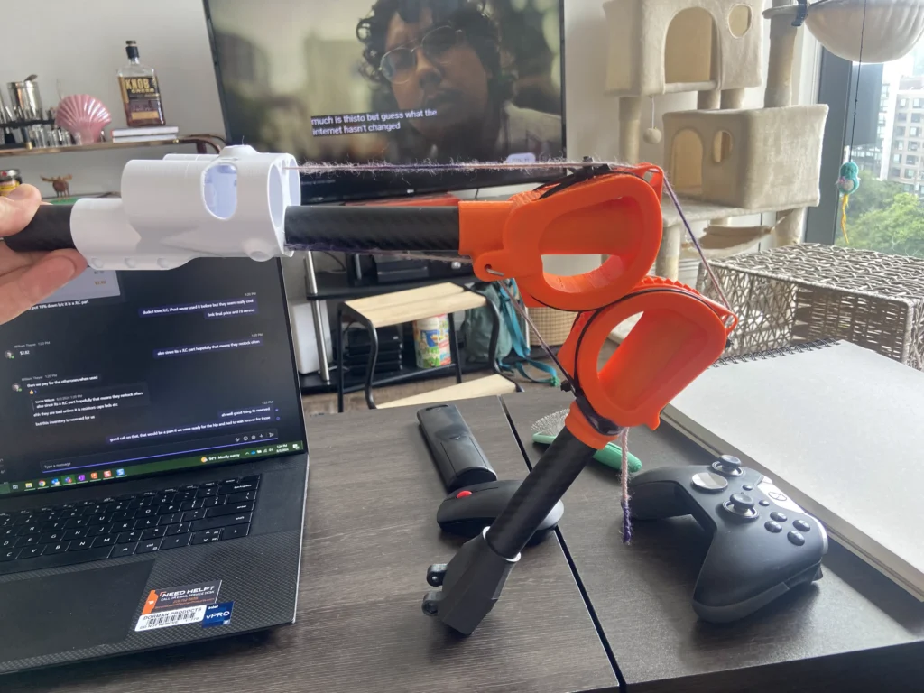
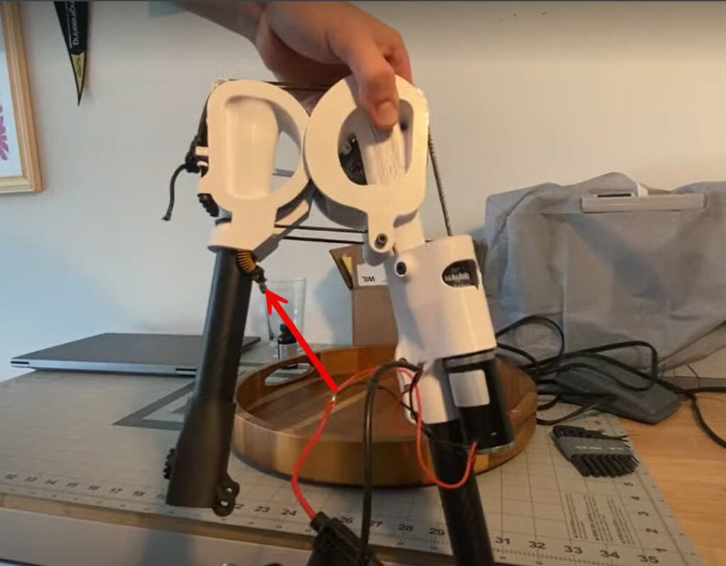
V2: Version 2 solved the rope falling off the side by adding fences to the outside to keep the rope in place. This was the first version that I managed to assemble and actuate using the motors, this allowed me to discover that the top tendon gap opened at a faster rate than the bottom gap closed. This means that when the joint is a full crouch the tension on the tendons increases so much that the joint binds up, and at full extension the tendons go slack to the point that the capstan drums cannot actuate the joint.
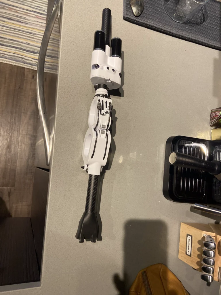
V3: This version attempted to solve the tension issue. I realized that the points where the tendon last make contact with the joint have to be equal distance from the center of rotation or else they travel different distances, so in this version I moved the pulley and the point where I tie the cord to the bottom knee. This helped but it did not solve the issue, I later realized that in order to completely solve this the break points would have to be both equal distance from center of rotation and 180 degrees apart
In the picture to the right you can see the blue line shows where the current break point is, and the bottom black line is where it needs to go to be 180 degrees away from the top break point.
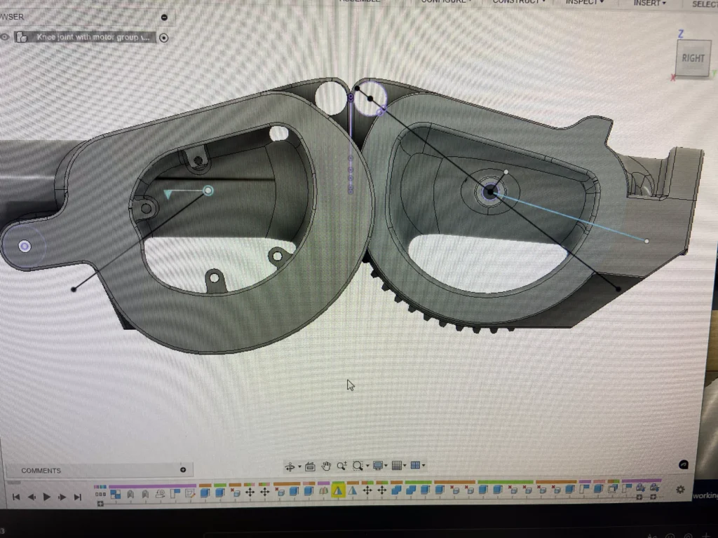
V3 pt 2: In order to continue testing the motion of the joint and the motor groups I came up with a simple temporary solution. I added a spring that will take up the slack when the joint is fully extended, this way the capstan will always have tension and the joint can move freely for it’s full travel, though it does get a bit tight at the fully compressed position
Capstan
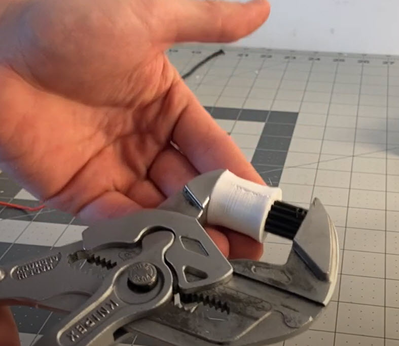
The capstan drum has gone through its own set of revisions. At first I copied Aaed Musa’s capstan which has a helical groove cut into it where the cord sits in. I found quickly that this design ends up feeding the wrapped loops of cord up and off the capstan, and upon falling off the drum the tendon loses tension. The next version I tried was a 3d printed drum where I drew inspiration from the capstan’s on sailboats. This drum is dished so that the cord naturally falls to the center of the drum. In order to drive this 3d printed plastic drum from an 8mm shaft at considerably high torque I couldn’t just press it on and use a set screw. Will Thayer came up with the idea of using a pinion gear designed to clamp onto the 8mm shaft, pressed into the 3d printed drum so that it acts as a spline drive. This worked incredibly well and I really like this solution but I found that the plastic drum tends to slip when the joint is heavily loaded. Below you can see the pinion gear being pressed into the dished drum.
The solution that I found works best was actually my very first plan for the capstan drive, a timing gear pulley. I found that the cord does not have an issue with bunching up or sliding up off the pulley, and I have not had any issues with the cord slipping on the pulley.
Knee motion, I2C and code testing
This has been an incredibly frustrating portion of the project and that’s to be expected for a project like this. Some call what I’m experiencing “Integration Hell”.
Things that I have discovered aren’t working include : I2c message handling, the potentiometer, the calibration command, the safe mode command, the safemode function, the reset function, the signal smoothing function. And to top it all off I can’t read the serial output of the motor controller Arduino while its installed on the leg because the programmer header is on the backside. I have been fighting compound issues for three days now and have been making mild progress but Will and I both knew long ago that a few changes to the PCB will make our lives a lot easier and solve a few of our issues. Before I dive into the V2 board though I do want to take a moment and say that the testing I have completed so far is very promising and gives me the energy to keep going. The knee joint is STRONG, like arm wrestling strong (ask me how I know), the motor controller works and the PID algorithm seems to work. I placed the end of the shin bine against my kitchen scale and held the other side and managed to blow past the scales 11 lb limit. If I had to guess I’d assume the knee is putting out about 22lbs of lift capacity. And at only 3.5 lbs for the knee and knee motor group I think this thing will have plenty of strength. proper weight and durability testing to come once I sort out the controller board
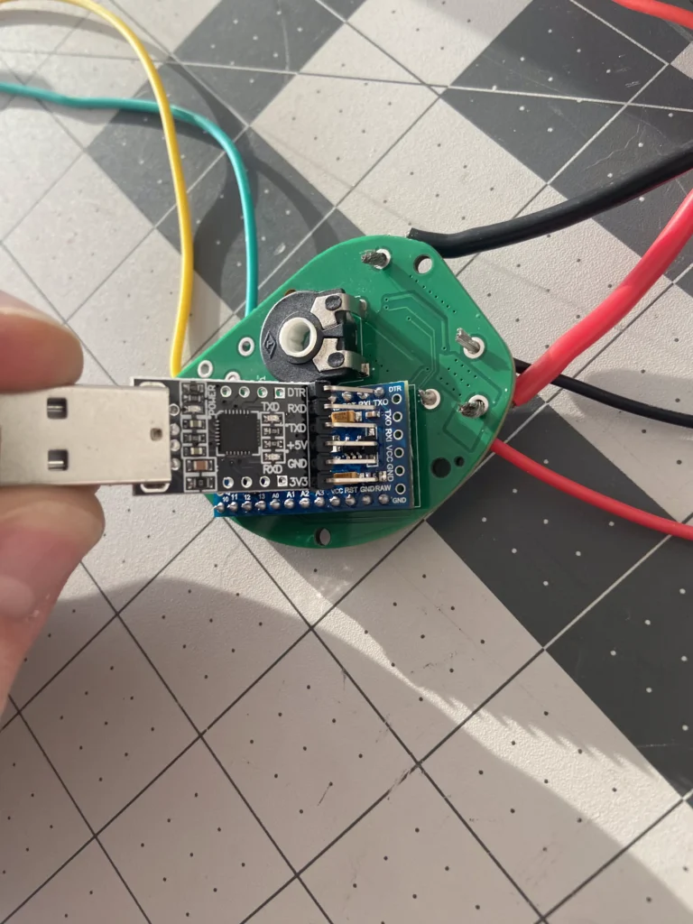
Since I was able to test some major components like the motor controller and the I2C functions I have decided to push forward with the V2 controller board. V1 had every wire soldered directly onto it, no access to programming headers, used a potentiometer for angle position, a non functional LED and a bunch of other issues. V2 has the following features:
- Arduino pro mini
- Pro mini programming pins
- Mounting holes
- Motor controller IC
- I2c booster IC (MFR P82B715DR )
- 2X 4 pin I2c port (do not connect 5v to the ‘duino)
- 3 pin JST connected to interrupt pin for PWM input from AS5600
- RGB led
- Motor current sense resistor (maximum 3.6 amps drawn by motor)
- 24 to 5v voltage regulator for the Arduino (and maybe a small cap to clean up its power since its feeding off the motors power)
- 2x Xt30 for power in and motor out
- JST 2 pin for foot sensor button input
- 4 output dip switch for setting I2c address
Assembled leg testing
I finally got around to printing and assembling an entire leg, it was a massive amount of work. I am still in the process of testing the leg and only built the test jig last weekend 10/13/24. I need to finish soldering all the wiring together for the I2c, power and motors before I can actually start testing, but dont worry updates will come shortly.
Downloads
You wouldn’t download a leg would you?
If you like this project and want to help support it please consider donating!



8 Responses
Hi, I’ve watched your video – ambitios project!
Here’s my two (or rather 3) cents: 1- use bldc motors with a descent controller. Moteus is excellent for that. 2. use CAN/ CAN-FD instead of I2C. 3. avoid ROS if you are not dependent on a specific libary that requires it.
Hey Jev, I completely agree with you on using BLDC motors, however, I am curious about your suggestion to avoid ROS. Care to elaborate more?
Nah, use ROS2 a great framework to learn, the learning curve is steep but rewarding the most important is that has so many packages that will ease the development
The only thing you need is a powerful computer, use and plan around a system such as Nvidia Xavier AGX or Orín AGX
Great article and video, moving forward. https://www.hackster.io/ivannestorovski1993/dc-motor-position-control-with-potentiometer-for-robotic-arm-6bd0e1 here is something you can modify for the position control, also i wrote some math on capstan or winch drives on https://hackaday.io/page/394965-winch-actuator-drive-mechanism i hope this can help.
Hello,
Great work,
I doing something similar, and im interested of building an actuator like you have in you robot leg. With strings/cables and a captan drive. So i will study this what you have done and try to replicate that.
The step file seems to be corrupted. I failed to open it in Bambu Studio and Fusion.
I may have missed it, but what was the reason for having dual motors for the capstan ? Does it have something to do with holding force ? Or just not having a motor with “dual” axle that could handle the other pulley ? Either way nice project I just didn’t understand that part.
Its been a while since I had to think about that decision so I can’t fully remember all the variables at play but I think it was mainly packaging. For the knee a single larger motor would have worked but I liked having the two smaller motors mounted closer to the “bone” of the leg, it more closely matched the shape of the muscle and have me a few extra degrees of inwards movement on the knee. For the hip I think the only reason I used two smaller motors is because they were cheaper to buy in bulk with the knee motors so I just stuck with them instead of picking out a different motor